English    |    Français

How does the PASCO Smart Cart Compare to the Vernier Go Direct® Sensor Cart?

Smart Cart Comparison Banner

How does the PASCO Smart Cart Compare to the Vernier Go Direct® Sensor Cart?

The Smart Cart may appear to be equivalent to competitors like Vernier’s Go Direct Sensor Cart–they include many of the same features and specifications–but several distinctions set the PASCO Smart Cart apart.

What’s the Same?

Both Measure:

  • Position
  • Velocity
  • Acceleration
  • Force

Both Feature:

  • Wireless software connection
  • Use on or off a track
  • Plunger

Both Include:

  • USB Cable
  • Rubber Bumper
  • Hook

What’s Different?

PASCO Includes More

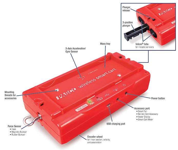
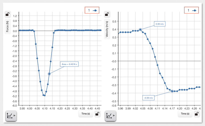
The PASCO Smart Cart comes with both hook and loop and magnetic bumpers. The magnetic bumper attaches to the force sensor, enabling you to measure the impulse during a collision. You must order bumpers separately for the Vernier sensor cart.
Smart Cart Callout

Why?

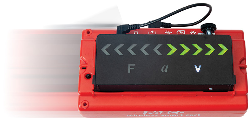
PASCO’s design makes it easy to launch the cart at 1x, 2x, and 3x velocities. With F, 2F, and 3F settings built-in to the Smart Cart, students can spend more time gathering data and solving for unknown variables and less time fiddling with cart settings.

This is important because you want to do more collisions, and with included bumpers, you can. Use the hook and loop tabs for inelastic collisions, magnetic bumper for elastic collisions, or unscrew the magnet and replace it with the rubber bumper for harder impacts.


Simple to Use Plunger

The Smart Cart plunger easily clicks into 3 different settings that correlate proportionally to 1, 2, and 3 units of force. By simply pressing the plunger to your desired setting, you can easily launch the Smart Cart at three different velocities that correlate to 1F, 2F, or 3F. Vernier’s plunger does not click into distinct velocity settings. What’s more, the total range of force on the Vernier cart is smaller than the range available to the Smart Cart, as you can only increase the force on the Vernier cart up to 1.3x.

Why?

PASCO’s design makes it easy to launch the cart at 1x, 2x, and 3x velocities. With F, 2F, and 3F settings built-in to the Smart Cart, students can spend more time gathering data and solving for unknown variables and less time fiddling with cart settings.

Larger Load Cell Capacity

PASCO’s Smart Cart load cell capacity is ±100N, double that of Vernier’s cart which is ±50N.

Why?

A larger load cell capacity means students are less likely to damage the sensor. Measure larger impulses and create collisions with higher impact. Since the sensor can withstand 100N, it is less likely to break during a tug-of-war demonstration of Newton’s 3rd Law.

Smart Cart Rubber Band Experiment

Sealed & Protected Encoder Wheel

PASCO’s encoder wheel is internal and connects to the axle of an existing wheel. Vernier’s encoder wheel is an exposed 5th wheel on the underside of their Sensor Cart.

Why?

A built-in optical encoder wheel means it is sealed and protected from everyday student use. It won’t fall victim to dust, grime, or student abuse, ensuring your data is as accurate as possible for kinematics studies.

Higher Encoder Sampling Rate

PASCO’s Smart Cart encoder maximum sampling rate is 500Hz. Vernier’s rate is 30Hz.

Why?

A higher sampling rate means you can collect more data points! This is important to match a higher sampling rate of the force sensor during impulse experiments.

Smart Cart Magnetic Collision

PASCO Doesn’t Manipulate the Data!

Vernier’s software performs data smoothing automatically so it cannot be turned off completely.

Why?

You’re a science educator who wants your students to collect and graph the real data, so that’s what we give you.

3-Axis Gyro

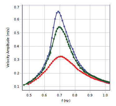
PASCO’s 3-axis accelerometer includes a 3-axis gyro, and Vernier’s 3-axis accelerometer does not.

Why?

The gyro allows you to measure angular velocity right out of the box so you can study centripetal force.
EX-5551 Graph

No Bumper Assembly Required

No classroom management or assembly is required to ensure the magnetic bumper is the correct orientation (north and south poles) for the Smart Cart. For the Vernier cart, you must assemble all magnetic and velcro bumpers separately, and make sure the four pieces for each Vernier cart are accounted for.
Smart Cart with Mass

Why?

Fewer pieces and minimal assembly means easier setup, easier cleanup, and less items to lose–giving you more time for investigations.


Bluetooth Time Sync Within & Between Carts

We’ve engineered our Smart Carts to time-synchronize all on-board sensors; In other words, force data syncs with velocity data from the encoder. Further, data also syncs between multiple carts in a collision so the data from both carts lines up. Vernier’s data is out of sync, and synchronization worsens as sampling rate increases.

Why?

Dependable time sync between carts means your data and graphs correlate with the phenomenon, making it easy for your students to interpret what their data is showing.

Proportional Smart Cart Masses

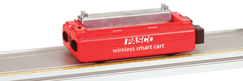
The Smart Cart and masses are proportional and stackable; the Smart Cart is 250 grams and the cart masses are each 250 grams. Vernier’s cart is 286 grams and the masses are 125 grams which creates strange multiples of total mass as you add masses.

        Why?

Stackable and proportional masses create conceptual demonstrations and easier numbers to work into equations, aiding students in understanding core concepts.
Force Velocity Graph

More Accessories Available

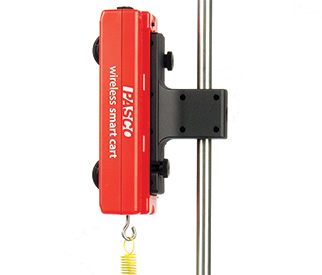
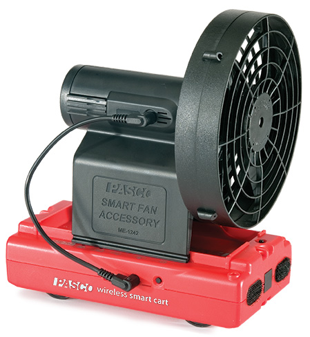
PASCO has several add-ons that pair seamlessly with our Smart Cart’s design, including a Smart Fan, Smart Ballistic Accessory, Rod Clamp, Vector Display, and Motor. Vernier does not offer any of these accessories.

Smart Cart with Fan

ME-1244 in use


Why?

Do more physics! PASCO’s accessories are designed to easily attach to the Smart Cart so students can examine core physics concepts. Also, when you connect a Smart Accessory to the Smart Cart, the Smart Cart can control the accessory for customizable investigations!
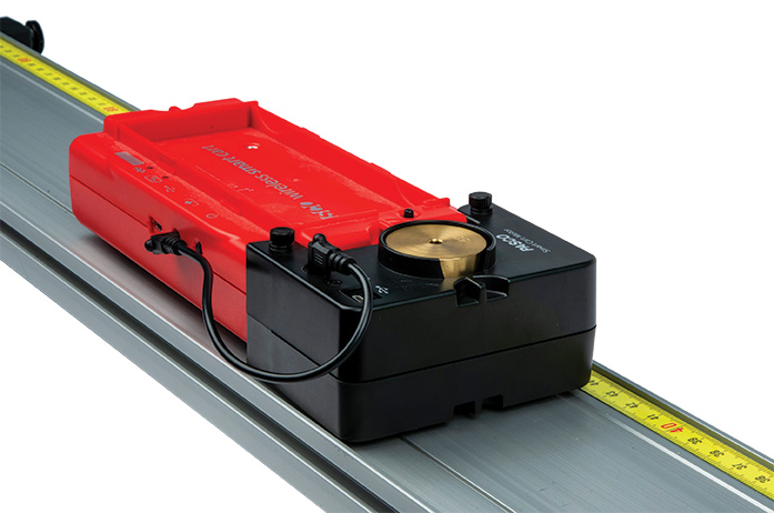
 

Smart Cart Front Track

ME-1246 View from Top


With an unparalleled design and countless applications in the physics lab, the PASCO Smart Cart will undoubtedly become one of your favorite teaching tools!

Assumption College Visit

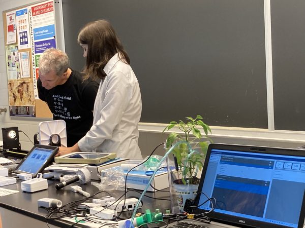
Yesterday we visited Department Head David Page and the Science Department at Assumption College School in Brantford, Ontario.

We demonstrated a variety of PASCO products including the newest additions, the Greenhouse Sense and Control Kit and PASCObot as well as PASCO classics including the Basic Optics System, and award-winning Smart Cart.

It was great to be back in person interacting with teachers! We discussed ways to integrate PASCO products into the classroom to create a fun, educational, and hands-on environment for students.
We were very impressed with Assumption College’s extensive PASCO collection and how they are using multi-generations of PASCO in tandem for their labs.

Thank you to David Page for arranging the visit and we are looking forward to visiting more schools in the future!

Coding with Blockly: Displaying a Smart Cart’s Velocity Vector

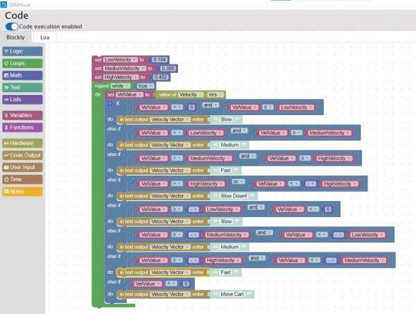
Today I got to work through an experiment using PASCO’s Wireless Smart Cart and Blockly code on SPARKvue.  I followed the Blockly Extension: Vector Display lab from the PASCO Experiment Library. This lab guides you to use Blockly code to display text on the screen depending on the speed of the Smart Cart.

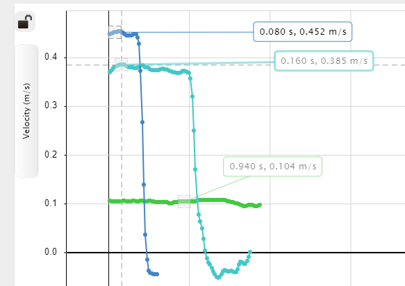
I connected the Smart Cart through Bluetooth to SPARKvue and read through the lab procedure. I started off by slowly moving the Smart cart along my desk while observing the velocity graph. I conducted three runs, one to determine a low velocity, a medium velocity, and a high velocity. I took note of these three velocities, as shown in the image on the right, so that they could be included within the code. After getting familiar with the lab, I copied the example code, adjusting the velocity values to the ones I recorded, as shown in the image on the left. I tested my code by clicking start and moving the Smart Cart. At first, I was not sure where to look for the displayed text. I realized I had to change my display from a graph to digits. Then, by clicking the variable being displayed, I switched from Sensors to User-entered and chose Velocity Vector (the variable I created in the Blockly code). This time when I pressed start, the vectors I assigned to each velocity displayed on the screen depending on the Smart Cart’s speed. I decided to change the text displayed from vectors to words. As shown in the video below, I used simple terms such as slow, medium, and fast to describe the carts’ velocities.

I found this lab super cool! It was my first time experimenting with the Wireless Smart Cart using Blockly code and I am looking forward to coding more products.

Work-Energy Theorem

  1. Take your Smart Cart out of the box.

  2. Turn it on and open your choice of software: SPARKvue or Capstone.

  3. Wirelessly connect to the Smart Cart.

  4. Change the sample rate of the Smart Cart Position and Force sensors to 40 Hz.

  5. Make a graph of Force vs. Position and another graph of Velocity vs. Time.

  6. Install the hook on the Smart Cart’s force sensor. Without anything touching the force sensor, zero the force sensor in the software.

  7. Put a rubber band on the force sensor hook. Start recording and while one person holds the rubber band in place, the other person slowly pulls the cart back, stretching the rubber band. Then hold the cart in place with the rubber band stretched and stop recording. Do not let go of the cart or rubber band.

  8. Start recording again. Let go of the cart and move the hand holding the rubber band out of the way. Let the cart go up to its maximum speed and then stop recording.

Analysis

  1. Determine the work done in stretching the rubber band by finding the area under the Force vs. Position curve.

  2. Determine the work done as the stretched rubber band pulls the cart by finding the area under the Force vs. Position curve.

  3. On the Velocity vs. Time graph, determine the maximum velocity. Calculate the kinetic energy of the cart and compare to the work done to accelerate the cart.

  4. Why isn’t the work done to stretch the rubber band equal to the work done to accelerate the cart?

Sample Data

The work done loading the rubber band is -1.91 Nm. The work done unloading (when the cart is launched) the rubber band is 0.77 Nm. The resulting kinetic energy of the cart is

KE = ½ mv2 = ½ (0.252 kg)(2.34 m/s)2 = 0.69 J. This is 10% less than the energy available in the stretched rubber band.

The energy stored in the rubber band is less than the work done to stretch the rubber band. Some of that energy goes into heating the rubber band and making the rubber band move.

Static and Kinetic Friction


  1. Take your Smart Cart out of the box.

  2. Turn it on and open your choice of software: SPARKvue or Capstone.

  3. Wirelessly connect to the Smart Cart.

  4. Make a graph of Force vs. Position.

  5. Make sure the Smart Cart Force sensor (with the magnetic bumper on it) is not touching anything and then zero the Force sensor in the software.

  6. Set the cart bumper against the book. Start recording. Very slowly push the cart until the book breaks loose and then push it steadily across the table. Stop recording.

  7. Take another run, pushing it at a faster speed once it breaks loose.

  8. Add a second book on top of the first book and repeat.

Analysis

  1. For each run, record the maximum force before the book moved. This is an indication of the static friction. If you can find the mass of the book, you can calculate the static coefficient of friction for the book on the table.

  2. For each run, record the average force while the book was moving. This is an indication of the kinetic friction. If you can find the mass of the book, you can calculate the kinetic coefficient of friction for the book on the table.

  3. What effect does speed have on the kinetic friction?

  4. What changes when the extra book is added? Do the coefficients of static and kinetic friction change?

Sample Data

The average kinetic friction for two books is 6.92 N.

The average kinetic friction for one book going slower vs. faster was 3.35 N compared to 4.19 N. This indicates that the speed does influence the kinetic friction slightly.

Mass of First Book = 1.56 kg

Mass of Second Book = 1.58 kg

For one book:

μs = F/mg = 3.09N/(1.56)(9.8) = 0.2

μk = F/mg = 3.17N/(1.56)(9.8) = 0.2

For two books:

μs = F/mg = 7.11 N/(1.56+1.58)(9.8) = 0.2

μk = F/mg = 6.59N/(1.56+1.58)(9.8) = 0.2

Hooke’s Law

Hooke’s Law states:
where F is the force of the spring, k is the spring constant, and x is the distance the spring has been stretched.

  1. Take your Smart Cart out of the box.

  2. Turn it on and open your choice of software: SPARKvue or Capstone.

  3. Wirelessly connect to the Smart Cart.

  4. Make a graph of Force vs. Position.

  5. Install the hook on the Smart Cart Force Sensor. Make sure the Smart Cart Force sensor is not touching anything and then zero the Force sensor in the software.

  6. Put one end of a spring on the hook and hold the other end stationary with your hand. Move the cart slightly to put a little tension on the spring.


  7. Start recording and pull the Smart Cart away from the fixed end of the spring until the spring is stretched out. Then stop recording.

Analysis

  1. On the Force vs. Position graph, apply a linear fit to the straight-line part of the graph.

  2. Determine the spring constant from the slope of the linear fit.

Sample Data


The slope of the graph indicates the spring constant is 6.77 N/m.

Impulse Demonstration

Equipment:

Smart Cart

Accessory Rubber Bumper

Learning Outcome:

A force acting on an object for a period of time imparts an impulse to that object which is defined as a change in momentum.

Experimental Setup:

  1. Take your Smart Cart out of the box

  2. Attach the rubber bumper accessory (included with Smart Cart) to the force sensor on the Smart Cart.

  3. Press the power button on the side of the Smart Cart to turn it on.

  4. In SPARKvue or Capstone, pair the Smart Cart to your computer or device. Here are a couple short videos to help you pair in either software:

    1. SPARKvue: https://www.youtube.com/watch?v=tsdHWu4quNo

    2. Capstone: https://www.youtube.com/watch?v=JGy-UG245lY

  5. In the software, you will need to create a graph of Force vs. Acceleration.

    1. In SPARKvue:

      1. Under “Quick Start Experiments” choose: Impulse

      2. Increase the sampling rate of the Force sensor to 1KHz

    2. In Capstone:

      1. Create two graph displays

      2. Graph 1: [Force] vs. Time

      3. Graph 2: [Velocity] vs. Time

      4. Increase the sampling rate of the Force sensor to 1KHz

You will push the cart into a barrier such that the rubber bumper will collide and bounce the cart off the barrier. A wall, book or other solid vertical surface will work.

Data Collection:

  1. Zero the force sensor

  2. Press the record data button

  3. With the rubber bumper facing towards the barrier, give the Smart Cart a push.

  4. After the Smart Cart has reversed direction, stop data collection.


Data Analysis:

  1. On the Force vs. Time graph, use the Area tool to measure the area under the curve. This is the impulse that the Smart Cart experienced.

  2. On the Velocity vs. Time graph, use the Coordinate tool to find the velocity just before the impact of the Smart Cart against the barrier and record this value. This is the Smart Cart’s initial velocity.

  3. Next, using the Coordinate tool find the velocity after the collision with the barrier. Record this value. This is the Smart Cart’s final velocity.

  4. Weigh the cart without any bumper and record the mass. You may also estimate the mass of the Smart Cart to be around 0.250 kg.

Calculate the change in momentum of the Smart Cart: pf – pi

Compare your calculated value to the area under the Force vs. Time graph.

Sample Data:

This data was created with a Smart Cart that measured 0.246 kg, for an error around 1.5%.

Centripetal Acceleration and Force

  1. Take your Smart Cart out of the box.

  2. Turn it on and open your choice of software: SPARKvue or Capstone.

  3. Wirelessly connect to the Smart Cart.

  4. Make a graph of Acceleration-x (from the Smart Cart Acceleration Sensor) vs. Angular Velocity-y (from the Smart Cart Gyro Sensor). Add a second plot area with the Force vs. Angular Velocity-y.

  5. Install the rubber bumper on the Smart Cart Force Sensor. With the cart sitting still, with nothing touching the rubber bumper on the Force Sensor, zero the Acceleration-x, Angular Velocity-y, and the Force in the software.

  6. Set up a board or track on a rotatable chair as shown in the picture. Set the end stop near the end of the track and place the cart’s rubber bumper (Force Sensor end) against the end stop.

    Post

  7. Spin the chair and start recording. Let the chair spin down to a stop and then stop recording.

  8. Apply a curve fit to the data to determine how the centripetal acceleration and force are related to the angular velocity. For the quadratic fit, open the curve fit editor at right in Capstone and lock the coefficient B = 0.

 This forces the fit to Aω2 + C. From the curve fit, what is the radius?

  1. In which direction are the centripetal acceleration and the centripetal force?

Further Study

  1. Move the end stop 5 cm closer to the center of rotation. Repeat the experiment.

  2. Continue to move the end stop closer to the center in 5 cm increments.

  3. How does the centripetal force depend on the radius?

Sample Data

Both the centripetal acceleration and the centripetal force are pointing toward the center of the circle (they are negative) and are proportional to the square of the angular velocity.

a = -0.383ω2 – 0.0530

F = -0.0966ω2 – 0.00596

m = 0.25 kg

F = ma = 0.25(-0.383ω2 – 0.0530) = -0.096ω2 – 0.013

The radius is 0.383 m because a = rω2.

Newton’s Second Law Demonstration

Equipment:

  • Smart Cart

  • Accessory Hook

Learning Outcome:

Forces and Accelerations of objects have a linear relationship that relates the mass of an object being accelerated to an unbalanced force acting on it.

Experimental Setup:

  1. Take your Smart Cart out of the box.

  2. Attach the hook accessory (included with Smart Cart) to the force sensor on the Smart Cart.

  3. Press the power button on the side of the Smart Cart to turn it on.

  4. In SPARKvue or Capstone, pair the Smart Cart to your computer or device. Here are a couple short videos to help you pair in either software:

    1. SPARKvue: https://www.youtube.com/watch?v=tsdHWu4quNo

    2. Capstone: https://www.youtube.com/watch?v=JGy-UG245lY

  5. In the software, you will need to create a graph of Force vs. Acceleration.

    1. SPARKvue: Under “Quick Start Experiments” choose: Newton’s Second Law

    2. Capstone:

      1. Create a Graph Display

      2. Select measurement of [Force] for the y-axis

      3. Select measurement of [Acceleration – x] for the x-axis

      4. In the sampling control panel, press the “Zero Sensor” button

Before you collect data, practice rolling the cart in a forwards and backwards motion by only holding on to the hook. You want to apply a force along the cart’s x-axis, and have the cart roll only along this direction. This is made easier using a PASCO track to keep the cart moving in one direction, but not necessary for the demonstration. (Hint: Try not to wiggle or knock the Smart Cart hook as this will result in extraneous data points.) 

Data Collection:

  1. Press the record data button

  2. Holding only the hook, roll the Smart Cart forwards and backwards in the x-direction.

  3. Repeat this motion a few times to generate enough data points to see the graphical relationship.

  4. Stop data collection

Data Analysis:

  1. Turn on the ‘Linear Fit’ tool

  2. This relationship shows that there is a proportionality constant between the unbalanced force, and the Smart Cart’s resulting acceleration.

  3. The proportionality constant is the mass of the cart.

Add mass to the Smart Cart and repeat data collection for the new system mass.

Sample Data:

This data was created with a Smart Cart that measured .246 kg, for an error around 2%.

Average and Instantaneous Velocity and Speed

  1. Take your Smart Cart out of the box.
  2. Turn it on and open your choice of software: SPARKvue or Capstone.
  3. Wirelessly connect to the Smart Cart. Change the sample rate of the Position Sensor to 40 Hz.
  4. Open the calculator in the software and make the following calculation:
‎speed‎=abs([Velocity, Red (m/s)‎])       with units of m/s
  1. Create a graph of Velocity vs. Time and add a second plot area of speed vs. Time and add a third plot area of Position vs. Time.
  2. Mark a starting point with a piece of tape.
  3. Start recording. Push the cart about 20 cm out and back, ending at the same point where you started.
Analysis
  1. On the Velocity vs. Time graph, find the maximum positive velocity.
  2. What is the instantaneous velocity at the point where you reversed the cart?
  3. What is the average velocity over the entire motion of the cart? Highlight the area of the Velocity vs. Time graph during the time of the motion and turn on the mean statistic.
  4. What is the average speed over the entire motion of the cart? Highlight the area of the speed vs. Time graph during the time of the motion and turn on the mean statistic.
  5. What is the difference between speed and velocity?
Sample Data
The instantaneous velocity when the cart reversed was zero.
The average velocity over the whole trip was zero because we started and stopped in the same place.
The average speed over the whole trip was 0.36 m/s.
Speed is a scalar that is the magnitude of the velocity. Velocity is a vector and has both magnitude (speed) and direction.
  • 1
  • 2
Save & Share Cart
Your Shopping Cart will be saved and you'll be given a link. You, or anyone with the link, can use it to retrieve your Cart at any time.
Back Save & Share Cart
Your Shopping Cart will be saved with Product pictures and information, and Cart Totals. Then send it to yourself, or a friend, with a link to retrieve it at any time.
Your cart email sent successfully :)